# Viewer Region
The viewer region is the primary visualization interface in Flow360 GUI, providing interactive 3D visualization capabilities for geometry inspection, mesh analysis, and results visualization.
# 📸 Example Views
# Geometry View Mode
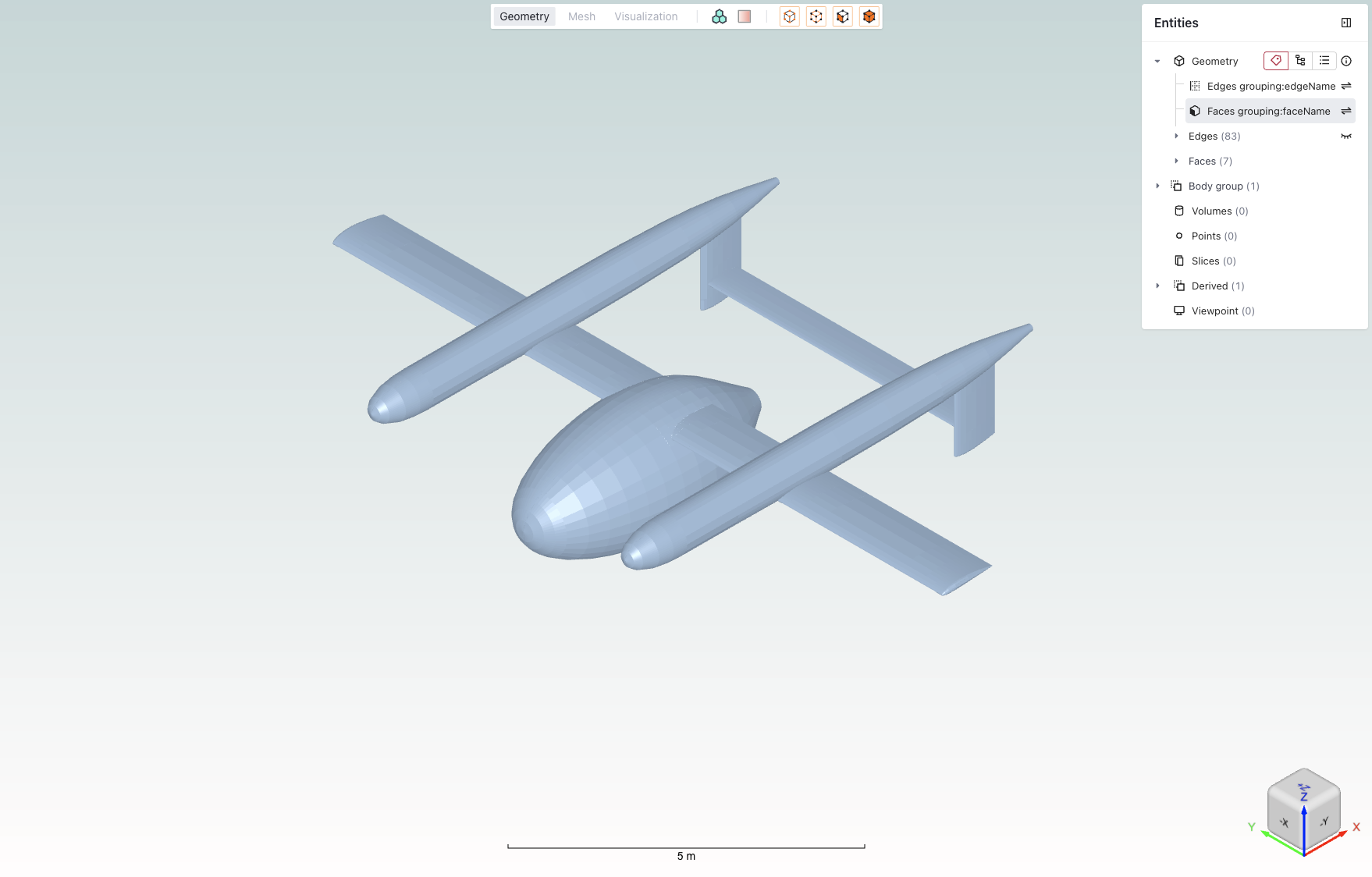 Example of the geometry view mode showing a CAD model with entity selection panel.
# Mesh View Mode
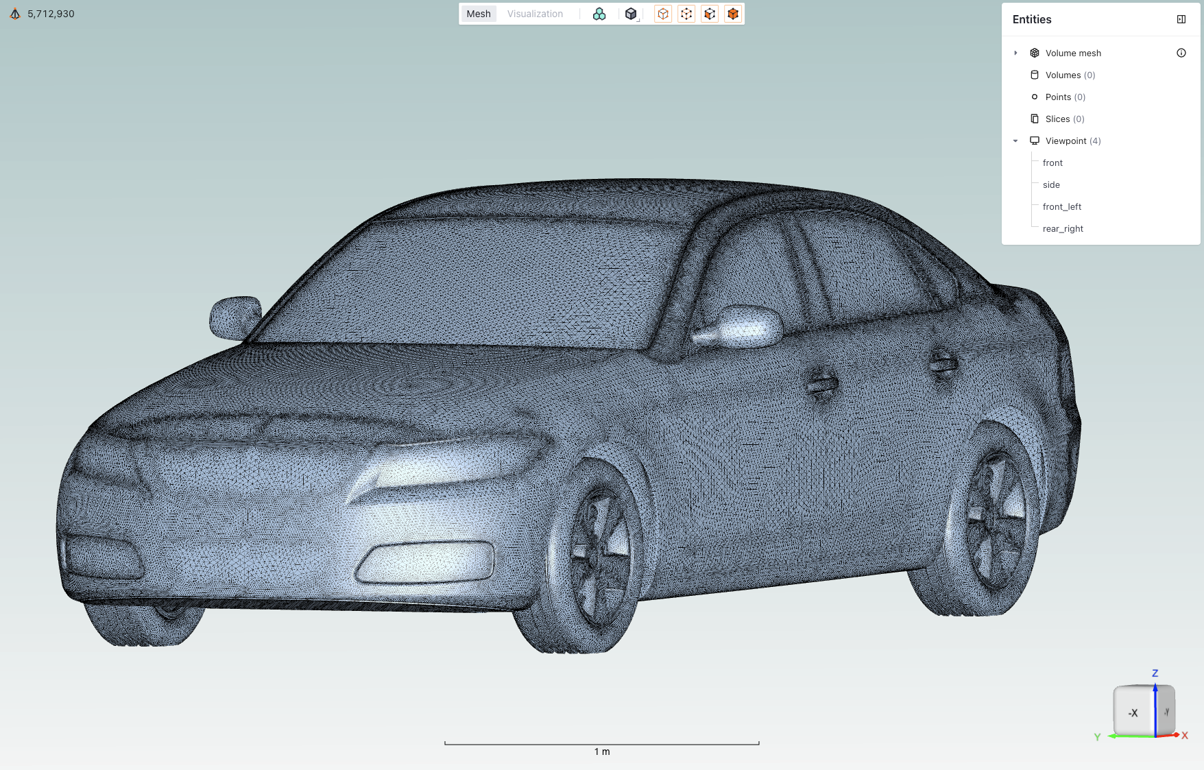 Example of the mesh view mode displaying a mesh visualization.
# Mouse Operations
Control viewport camera and model interaction using mouse inputs.
- Left Mouse Button: Rotate the view around pivot point
- Right Mouse Button Click: Opens a view menu with options including:
- Hide/Show controls for visibility
- View adjustment options (Reset view, Fit view)
- Fit to specific elements (selected, walls, farfield)
- Toggle features (origin point, legend)
- Access to saved viewpoints
- Right Mouse Button Hold: Pan the view
- Mouse Wheel: Zoom in/out
- Notes: Hold Shift while rotating to snap to principal axes
# 📋 Core Features
| Feature | Description | Icon |
|---|---|---|
| View modes | Toggle between Geometry/Mesh/Visualization views | |
| Boundary conditions | Toggle coloring of boundaries based on their assigned boundary condition | |
| Diagnostic tools | Geometry quality inspection features | |
| Mesh display | Mesh display options | |
| Entity selection mode | Tools for selecting and managing geometry entities | |
| Entities visibility | Toggle the visibility of entities by clicking the eye icon when hovering over them | |
| Mesh metrics | Expand the mesh metrics view by clicking on the icon when in mesh view | |
| Viewpoints | Controls for saving and loading specific camera positions | |
| Length scale indicator | Visual reference showing model dimensions to help maintain perspective | |
| Rotation cube | Interactive orientation widget for quick view rotation to standard angles |
# 🔍 Detailed Descriptions
# View modes
Toggle between Geometry/Mesh/Visualization views using top toolbar tabs.
- Geometry: View CAD geometry
- Mesh: Inspect surface and volume mesh
- Visualization: View simulation results and post-processing
Note: Each mode provides context-specific tools and options.
# Boundary conditions
Toggle coloring of boundaries based on their assigned boundary condition.
Note: Helps verify boundary condition assignments before mesh generation.
# Diagnostic tools
Tools for geometry quality inspection and validation that color areas of geometry depending on their level of confidence.
# Mesh display
Control the visualization of mesh elements and their properties. Can be set as either solid or solid with edges.
# Entity selection mode
Tools for selecting and managing geometry entities.
| Entity Type | Icon | Description |
|---|---|---|
| Points | Select individual points/vertices | |
| Edges | Select edge elements | |
| Faces | Select face/surface elements | |
| Volumes | Select volume elements |
Note: You can use any combination of selection modes.
# Entities visibility
Toggle the visibility of entities by clicking the eye icon when hovering over them.
# Mesh metrics
Quantitative mesh quality assessment tools for analyzing both surface and volume mesh characteristics.
# Element types overview
The mesh quality visualization provides statistics for different element types commonly found in CFD meshes:
Nodes are present in every mesh and represent the intersection points of mesh elements, they are fundamental to defining the mesh structure and geometry.
Surface Elements:
- Triangles: Primary surface mesh elements
- Quadrilaterals: Optional structured surface elements
Volume Elements:
- Tetrahedrons: Unstructured volume elements
- Prisms: Boundary layer elements
- Pyramids: Transition elements between different element types
- Hexahedrons: Structured volume elements
# Surface metrics
Key metrics for assessing surface mesh quality:
| Metric | Description | Importance |
|---|---|---|
| Area | Face area of surface elements | Identifies areas of highly non-uniform mesh resolution |
| Area Ratio | Ratio between adjacent face areas | Indicates mesh growth rate and smoothness |
| Aspect Ratio | Ratio between longest and shortest edge | Measures element skewness and potential numerical issues |
| First Layer Height | Height of first prismatic layer | Critical for boundary layer resolution |
# Volume metrics
Essential metrics for volume mesh quality assessment:
| Metric | Description | Importance |
|---|---|---|
| Aspect Ratio | Element shape quality indicator | Identifies highly stretched or compressed elements |
| Volume | Element volume measurement | Helps detect very small or large elements that might affect solution stability |
# Viewpoints
Controls for saving and loading specific camera positions.
- Usage:
- Click the + icon to add a new viewpoint that will be the current camera position
- Name the viewpoint to be representative of the camera position
# Length scale indicator
Visual reference showing model dimensions to help maintain perspective.
- Features:
- Dynamic scale adjustment
- Unit system consistency
- Reference dimension display
# Rotation cube
Interactive orientation widget for quick view rotation to standard angles.
- Usage:
- Click cube faces for orthogonal views
- Click vertices or edges for isometric views
💡 Tips
- Use keyboard shortcuts (Ctrl/Cmd) with mouse operations for enhanced control
- Save frequently used viewpoints for quick access
- Customize entity visibility to focus on areas of interest
- Use the fit-to-view option when navigating large models
❓ Frequently Asked Questions
How can I reset the view if I get disoriented?
Use the "Fit to Screen" option in the view menu.
Why can't I select certain entities?
Verify that the correct entity type is enabled in the selection toolbar.
How do I save a custom viewpoint?
Use the "Save Viewpoint" option in the View context menu after positioning the view as desired.